DC Power
Parts of PS
index > DC Power > Parts of PS
Emerson ER22020/T (ER11040/T) Rectifier Module
editor:admin date:2014-07-22
The Emerson rectifiers comprise two parts: 3-phase passive PFC and DC/DC converter circuit. Besides, there are the auxiliary power supply and the I/O detection protection circuit. The operation principle of rectifiers is shown in Figure ER22020/T
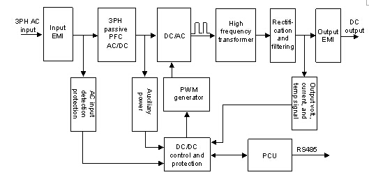
Rectifier operation principle of ER22020/T
1) The 3-phase passive PFC circuit at the front-end comprises input EMI and passive PFC, which are used to rectify and filter the AC input, and to calibrate the input current, so as to ensure that the power factor of the input circuit is bigger than 0.94, meeting the related EMI and EMC standards in GB/T 17794.2.2-2003, as well as the 3-phase harmonic standard in DL/T781-2001.
2) The DC/DC converter circuit at the back end uses PWM generator to control the PFC-output DC voltage, and output DC voltage through high frequency transforming, rectification and filtering. It is used to convert the rectified voltage from the front end into the steady DC voltage output as required by the power system.
3) The auxiliary power supply is located between the input passive PFC and the DC/DC converter. It uses the DC output from the 3-phase passive PFC and powers the control circuits.
4) The input detection circuit can detect input over/under-voltage and phase failure, while DC/DC detection circuit can detect output voltage/current and heat sink temperature. All these signals are used for the control and protection of DC/DC conversion.
Major Functions of ER22020/T(ER11040/T ,Emerson)
1. Protection
1) Input over/under-voltage protection
The rectifiers are capable of over/under-voltage protection. When the input voltage is smaller than the set under-voltage or bigger than the over-voltage, the rectifier will be shut down for protection. There will be no DC output, and the protection indicator (yellow) will turn on. The rectifier will return to normal operation when the voltage returns normal.
2) Output over-voltage protection & under-voltage alarm
The rectifiers are capable of output over-voltage protection and under-voltage alarm. When the output voltage is higher than the preset over-voltage, the rectifier will shut down, with no output, and the alarm indicator (red) will turn on. The rectifier cannot be auto-reset. You need to power it off and on to reset it.
When the output voltage is lower than the preset under-voltage, the alarm will be raised, but the rectifier will keep its output, and the protection indicator (yellow) will turn on. This alarm will be cleared once the voltage restores to normal.
3) Short circuit foldback of output
The rectifiers are capable of limiting output upon short circuit, during which the output current will be limited to 40% of rated output current. The output will restore to normal after the short is removed.
4) Phase failure protection
The rectifiers are capable of phase failure protection. Upon input phase failures, the rectifiers will derate and output half power. The output current is 5A at the output voltage of 260V.
5) Over-temperature protection
The over-temperature protection will be triggered when the temperature is higher than the set point, either due to too high ambient temperature, or because rectifier air inlet is blocked. The Protection Indicator (yellow) on the rectifier front panel will turn on, and there will be no output. This protection can be reset automatically when abnormality is cleared and rectifier internal temperature restores to normal.
6) Front-end over-current protection
This protection will be triggered upon over-current at the rectifier’s rectification part. It cannot be reset automatically. To reset it, you need to power it off and on.
2. Other functions
1) Fan speed control
There are 3 classes of fan speed: stop, half-speed and full speed, determined by taking both temperature and output current into consideration.
2) Fault display
Upon rectifier faults, the alarm information will real-time flash on LED in the form of fault code. You can switch the display content to voltage by pressing the A/V button (current/voltage display switching button).
3) Communication function
The rectifier can communicate with the host through RS485 port. It can report to the host its output voltage, current, protection and alarm information, as well as receive and execute control orders from the host.
More information refer to www.emerson-cn.com
Specifications of Emerson ER22020/T, and ER11040/T Rectifier Module
|
Type
|
Parameter
|
|
ER22020/T
|
|
ER11040/T
|
||
|
Input
|
Input voltage
|
323V ~ 475V (3ph 3 wire system)
|
|||||
|
Input current
|
|
≤ 15A
|
|
≤ 15A
|
|||
|
AC input frequency
|
45Hz ~ 65Hz
|
||||||
|
Efficiency
|
92%
|
≥93%
|
%
|
≥93%
|
|||
|
Power factor
|
0.94
|
||||||
|
Output
|
Output voltage range
|
176V ~ 320V
|
88 ~ 160V
|
||||
|
Rated output current
|
|
20A
|
|
40A
|
|||
|
Max. output current
|
|
21A
|
|
42A
|
|||
|
Soft start time
|
3 ~ 8s
|
||||||
|
Output constant current range
|
|
10% ~ 100%
|
|
10% ~ 100%
|
|||
|
Current stabalization (for 20% rated current or above)
|
≤ ± 0.5%
|
||||||
|
Ripple
|
≤ 0.1%
|
||||||
|
Voltage stabalization
|
≤ ± 0.5%
|
||||||
|
Load sharing imbalance
|
≤ ± 5%, (typical 3%, 50% ~ 100% rated load)
|
||||||
|
Accoustic noise
|
<55dB
|
||||||
|
Protection
|
Short circuit foldback of output
|
Foldback current ≤ 40% rated current. Auto-reset enabled
|
|||||
|
Output over-voltage protection
|
325 ± 5Vdc
|
165 ± 5Vdc
|
|||||
|
Output under-voltage protection
|
198 ± 1Vdc
|
99 ± 1Vdc
|
|||||
|
Input over-voltage
|
Protection point
|
485 ± 10Vac
|
|||||
|
Recovery point
|
460 ± 15Vac
|
||||||
|
Input under-voltage
|
Protection point
|
313 ± 10Vac
|
|||||
|
Recovery point
|
335 ± 10Vac
|
||||||
|
Over-temperature protection
|
Protection point
|
80°C
|
|||||
|
Recovery point
|
60°C
|
||||||
|
Fan speed control
|
Under the combined control of temperature and current
|
||||||
|
Safety
|
Insulation resistance
|
I/O to chassis and input to output >10MΩ (Test voltage: 1000Vdc)
|
|||||
|
Dielectric strength
|
Impose AC between I/O and the chassis aftering shorting the input and output. Frequency: 50Hz. RMS: 2000V. No breakdown or flashover
|
||||||
|
Environment
|
Operation temperature
|
-10°C ~ 40°C
|
|||||
|
Storage temperature
|
-25°C ~ 55°C
|
||||||
|
Relative humidity
|
≤ 95%
|
||||||
|
Air pressure
|
70 ~ 106kPa
|
||||||
|
Mechanical
|
Size (L × W × H) (Unit: mm)
|
|
388×88×241
|
|
388×88×241
|
||
|
Weight
|
|
8kg
|
|
8kg
|
|||
|
Cooling method
|
Forced cooling, with dust proof design
|
||||||