DC Power
Parts of PS
index > DC Power > Parts of PS
Emerson PSM-E20 Monitoring System
editor:admin date:2014-07-22
System Architecture of PSM-E20
The PSM-E20 monitoring system architecture is shown in the following figure. The numbers in the brackets are the numbers of the corresponding parts that can be connected to the system.
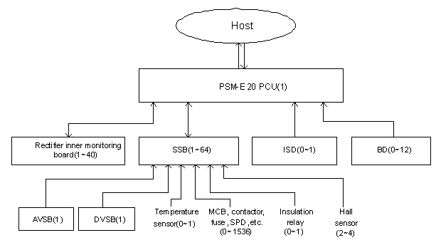
As shown in the figure, the core part of the monitoring system is PSM-E20 PCU, which collects information from downstream monitors, and, after analysis and calculation, displays the information, raises alarms or send control commands to the downstream monitors. Through communication protocol Modbus, CDT91, DNP3.0, IEC101, or IEC103, the PCU can also send the information to and receive control orders from the host, in order to realize the unattended operation of the power system.
Through the large LCD and the keypad on the front panel of the PCU, you can set parameters and check history records.
A built-in monitor board monitors the rectifier. It can collect the rectifier’s analog signal such as output voltage and current, as well as the digital signal such over-temperature, protection and faults, and report them to the PCU. The monitor board also receives orders from PCU and executes them.
It is the distribution monitoring-box that monitors the system power distribution. After receiving the analog signals from AC/DC sampling board (which transforms high voltage signal into low voltage signal), Hall sensor (which converts load current and battery current into low voltage DC), and temperature sensor (which converts temperature into low voltage DC), the distribution monitoring-box will process the signals and send them to PSM-E20 PCU. Meanwhile, the distribution monitoring-box will collect directly the digital signals from the power distribution and send them to PCU. There are two models of distribution monitoring-box: PFU-12 and PFU-13. The former one can monitor 17 analog signals, 26 digital signals and 4 dual-function signals, while the latter can monitor 24 digital signals.
It is the insulation status detector (IMS) or insulation relay that monitors the insulation of the power system. The insulation relay can observe the status change of its contacts when the system bus insulation deteriorates and report it to PSM-E20, which will raise the alarm of ‘Bus insu fault’. While the IMS can, when bus insulation deteriorates to a certain set level, find the faulty branch and report the information to PCU, which will raise the alarm of ‘Bus insu fault’ and the poor insulation alarm of the corresponding branch. See section Insulation Status Detector for details.
The battery detector (BMS) monitors the battery. It will convert the battery cell voltage signal and send it to PCU.
Detected Signals
Listed in Table PSM-E20-1 and Table PSM-E20-2 are the analog and digital signals that can be detected.
Table PSM-E20-1 Analog signals that can be detected
|
SN
|
Signal
|
Signal number
|
Detectable range
|
|
1
|
AC voltage
|
2
|
0 ~ 500V
|
|
2
|
Bus voltage
|
2
|
0 ~ 275V
|
|
3
|
Battery string voltage
|
2
|
0 ~ 275V
|
|
4
|
Load current
|
2
|
0 ~ 3000A
|
|
5
|
Battery current
|
2
|
-3000A ~ +3000A
|
|
6
|
Battery ambient temperature
|
1
|
-25°C ~ 100°C
|
|
7
|
AC/AC voltage
|
1
|
0 ~ 400V
|
|
8
|
AC/AC current
|
1
|
0 ~ 4000A
|
|
9
|
DC/AC voltage
|
1
|
0 ~ 400V
|
|
10
|
DC/AC current
|
1
|
0 ~ 4000A
|
|
11
|
DC/DC voltage
|
1
|
0 ~ 400V
|
|
12
|
DC/DC current
|
1
|
0 ~ 4000A
|
|
13
|
Single battery cell voltage
|
216
|
Tested as two groups
|
|
14
|
Insulation resistance and capacitance at the output branches
|
384
|
-
|
Table PSM-E20-2 Digital signals that can be detected
|
SN
|
Signal
|
Signal number
|
State
|
|
1
|
Output branch MCB state
|
24%64
|
Normally open or closed (configurable)
|
|
2
|
Battery fuse state
|
2
|
Normally closed
|
|
3
|
Insulation relay alarm state
|
1
|
Normally open
|
|
4
|
AC MCB trip alarm signal
|
1
|
Normally closed
|
|
5
|
AC contactor work state signal
|
2
|
Normally closed
|
|
6
|
SPD fault signal
|
1
|
Normally closed
|
|
7
|
AC/AC faulty
|
1
|
Normally closed
|
|
8
|
DC/AC faulty
|
1
|
Normally closed
|
|
9
|
DC/DC faulty
|
1
|
Normally closed
|
Function of PSM-E20 (Emerson)
The monitoring system with PSM-E20 PCU can fulfill the following functions:
Battery management
At power plants and substations, the DC power supply not only provides relays with constant DC power, but also feeds the switching coils of circuit breakers with surge current. Being an important element in DC power supply, the battery group requires advanced management. In the PowerMaster power system, the battery management uses a two-layer monitoring mode to on-line monitor the battery parameters, including cell voltage, charge/discharge current, and ambient temperature. Being intelligent and attendance free, its functions include:
Generally speaking, the battery management system transfers battery from float charge (FC) to BC based on the battery charge current, and from BC to FC based on the charge current and time. When equipped with a temperature sensor, the system can make temperature compensation to the FC voltage. Based on the battery current and total load current, the system can ensure the charging effect and prolong the battery life span by adjusting rectifier output current and current limit to control battery current and voltage, and prevent battery over charging-current. However, to realize the automatic functions, the rectifiers must be set to the Auto state.
The PCU carries out intelligent battery management in the following working states: 1. Normal charging statel Setup functionThe battery BC voltage and FC voltage are user configurable. You can set the parameters according to the battery model and voltage flexibly. After the BC and FC voltages are set, the PCU will regulate the battery terminal voltage to the set value according to the present BC or FC state. It should be pointed out that, if communication interruption occurs to a rectifier on the switching bus, the rectifier will enter the protection mode, and the output voltage will decrease to 234V/117V. The rectifier will return to normal operation after the communication restores. l Temperature compensationYou can decide whether or not the temperature compensation should be made to the FC voltage, as well as the center point and temperature compensation coefficient. After the parameter are set, the PCU will regulate the FC voltage according to the ambient temperature in the battery chamber to ensure normal battery operation temperature. l Capacity analysisYou can adjust the battery capacity calculation by setting battery charge efficiency and discharge characteristic curve. The PCU can calculate the battery capacity once every 15 seconds according to the battery current, battery charge or discharge state and coefficient. The capacity change will be displayed on the LCD in real-time. l Auto-operation combined with manual-operation ;PCU can work in either the Auto or Manual mode. In the Auto mode, the PCU can complete all the functions automatically. In the Manual mode, the battery management is controlled by maintenance personnel, who can, through menu operation, control the BC and FC switchover, regulate voltage and rectifier current limit, and power on/off the rectifiers. In the manual mode, the PCU will only collect the rectifier data through communication, and calculate the battery capacity. It will not control the rectifier, conduct BC and FC switchover, neither will it start the timed BC. For too long BC may shorten the battery life span, the PCU in Manual mode will monitor the BC time automatically and transfer the battery to FC state when the BC time exceeds the preset Timed-BC Time. ;2. Timed BC state3. BC after battery discharge 4. Other battery management functions
Alarm
Upon system abnormality, the monitoring system will raise alarm through the PCU LCD, the alarm indicator on PCU front panel, the alarm indicator on the electric power system, and the buzzer. Furthermore, the six alarm relays on the PCU will send alarm signals to the remote terminal, and, when in connection, to the host. The alarms that the monitoring system can raise are listed in Table 3-3.
Communication with the host
The monitoring system communicates with the integrated automation system through RS232/RS485 port. As for the communication protocol, you can select Modbus, CDT91, DNP3.0, IEC101 or IEC103 according to the actual situation.