Parts of PS
index > DC Power > Parts of PS

Emerson PSM-E10 (PSM-E10) Monitoring System

editor:admin    date:2014-07-22

System Architecture of Emerson PSM-E11

The PSM-E11 monitoring system architecture is shown in the following figure. The numbers in the brackets are the numbers of the corresponding parts that can be connected to the system. 


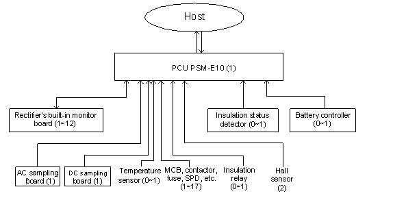
PCU PSM-E11 has built-in distribution monitoring-box, which directly collects signals from the AC/DC power distribution. As shown in the figure, the core part of the monitoring system is PSM-E11 PCU, which collects information from downstream monitors, and, after analysis and calculation, displays the information, raises alarms or sends control commands to the downstream monitors. Through communication protocol Modbus, CDT91, DNP3.0, IEC101, or IEC103, the PCU can also send the information to the host, and receive control orders from which, in order to realize the unattended operation of the power system. 

Through the large LCD and the keypad on the front panel of the PCU, you can set parameters and check history records.
A built-in monitor board monitors the rectifier. It can collect the rectifier’s analog signal such as output voltage and current, as well as the digital signal such over-temperature, protection and faults, and report them to the PCU. The monitor board also receives orders from PCU and executes them.
It is PSM-E11 PCU that directly monitors the system power distribution. PSM-E11 PCU receives signals directly from AC sampling board and DC sampling board (which transforms high voltage signal into low voltage signal), Hall sensor (which converts load current and battery current into low voltage DC), and temperature sensor (which converts temperature into low voltage DC). The PCU also collects the digital signals directly from the power distribution and processes them. 
The IMS or insulation relay monitors the insulation of the electric power system. The insulation relay can observe the change in the status of its contacts when the system bus insulation deteriorates and report it to PSM-E11, which will raise the poor bus insulation alarm. While the IMS can, when bus insulation deteriorates to a certain set level, find the faulty branch and report the information to PCU, which will raise the poor bus insulation alarm and poor insulation alarm of the corresponding branch. See section Insulation Status Detector for details.
The BMS monitors the battery. It will convert the battery cell voltage signal and send it to PCU.
More information refer to www.emerson-cn.com or www.goshenelectric.com.cn
Function of Emerson PSM-E11(PSM-E10)
The monitoring system with PSM-E11  PCU can fulfill the following functions:
Battery management
At power plants and substations, the DC power supply not only provides relays with constant DC power, but also feeds the switching coils of circuit breakers with surge current. Being an important element in DC power supply, the battery group requires advanced management. In the PowerMaster power system, the battery management uses a two-layer monitoring mode to on-line monitor the battery parameters, including cell voltage, charge/discharge current, and ambient temperature. Being intelligent and attendance free, its functions include: Calculating the battery capacity change according to the battery charge/discharge situation. Carrying out current-limit boost charge (BC) automatically according to the preset conditions after the battery discharge. Carrying out normal battery BC by controlling the bus voltage. Carrying out timed battery BC and BC/FC voltage temperature compensation automatically.
Generally speaking, the battery management system transfers battery from float charge (FC) to BC based on the battery charge current, and from BC to FC based on the charge current and time. When equipped with a temperature sensor, the system can make temperature compensation to the FC voltage. Based on the battery current and total load current, the system can ensure the charging effect and prolong the battery life span by adjusting rectifier output current and current limit to control battery current and voltage, and prevent battery over charging-current.. However, to realize the automatic functions, the rectifiers must be set to the Auto state.
The PCU carries out intelligent battery management in the following working states: 
1. Normal charging state
The PCU will automatically record the start point of BC and FC. If power failure or fault occurs to the system whose batteries are in the BC state, whether in the current-limit stage or constant-voltage stage, the PCU will let the batteries continue in that BC stage after power on or system reset. A battery in current-limit BC will transfer to constant-voltage BC automatically when the charging voltage reaches the level of constant-voltage BC. 
The PCU will also transfer the battery from FC to BC automatically if the FC current is bigger than the set value (to-BC reference current).
When the BC current is above the current limit set by the PCU, the battery is in constant-current BC, and the battery voltage will build up with the passage of time. When the battery voltage rises to a certain level, the BC will enter the constant-voltage stage, where the current will decrease gradually. Starting from the point when the charging current decreases to 0.01C10A (Stable-Current BC start point, as shown by the green dot in Figure 3-2, user defined), the constant-voltage BC ends three hours (Stable-Current BC Time, user defined) later, the battery transfers to the FC state, and the normal charging
2. Timed BC state
You can decide whether or not timed BC shall be used, as well as the interval and how long each BC lasts. When such parameters are set, the battery management program can make automatically the time table for battery timed BC, including the start point and end point. The O&M personnel can monitor the process through the PCU LCD onsite, or through the host at a remote monitoring center. Generally the BC should be repeated every 30 days, and each BC should last 24 hours. However, upon special occasions, the timetable should be set according to the battery’s instruction manual. 
3. BC after battery discharge
The battery will discharge upon AC power failure. When the AC restores to normal, the PCU will set the rectifiers to start BC if the battery current is bigger than the preset value (transfer-to-BC Reference Current). The precondition for the above function is that in the software setup of the PCU, the transfer-to-BC condition is set to battery current.
4. Other battery management functions
l Setup function
The battery BC voltage and FC voltage are user configurable. You can set the parameters according to the battery model and voltage flexibly. After the BC and FC voltages are set, the PCU will regulate the battery terminal voltage to the set value according to the present BC or FC state. It should be pointed out that, if communication interruption occurs to a rectifier on the switching bus, the rectifier will enter the protection mode, and the output voltage will decrease to 234V/117V. The rectifier will return to normal operation after the communication restores.
l Temperature compensation
You can decide whether or not the temperature compensation should be made to the FC voltage, as well as the center point and temperature compensation coefficient. After the parameter are set, the PCU will regulate the FC voltage according to the ambient temperature in the battery chamber to ensure normal battery operation temperature. 
l Capacity analysis
You can adjust the battery capacity calculation by setting battery charge efficiency and discharge characteristic curve. The PCU can calculate the battery capacity once every 15 seconds according to the battery current, battery charge or discharge state and coefficient. The capacity change will be displayed on the LCD in real-time.   
l Auto-operation combined with manual-operation
The PCU can work in either the Auto or Manual mode. In the Auto mode, the PCU can complete all the functions automatically. In the Manual mode, the battery management is controlled by maintenance personnel, who can, through menu operation, control the BC and FC switchover, regulate voltage and rectifier current limit, and power on/off the rectifiers. In the manual mode, the PCU will only collect the rectifier data through communication, and calculate the battery capacity. It will not control the rectifier, conduct BC and FC switchover, neither will it start the timed BC. For too long BC may shorten the battery life span, the PCU in Manual mode will monitor the BC time automatically and transfer the battery to FC state when the BC time exceeds the preset Timed-BC Time.
l Fault handling
When DC power system is abnormal, the PCU will set the battery to FC and trigger the current limit for all rectifiers until the system is normal again in order to protect the battery from over-charging and balance the needs of the load. Such abnormalities include bus voltage abnormal, distribution monitor board offline in the output cabinet, and battery fuse broken.
Alarm
Upon system abnormality, the monitoring system will raise alarm through the PCU LCD, the alarm indicator on PCU front panel, the alarm indicator on the electric power system, and the buzzer. Furthermore, the six alarm relays on the PCU will send alarm signals to the remote terminal, and, when in connection, to the host. The alarms that the monitoring system can raise are listed in Table PSM-E11,PSM-E10
Names and max. number of alarms in monitoring system
Alarm display
Alarm description
Max. number
Output branch off
Output branch trip
1536
batt fuse fault
Battery fuse broken
2
SPD fault
 
1
Bus insu fault
Bus insulation deteriorated
2
Output branch insu fault
Output branch insulation deteriorated
384
AC/AC fault
 
1
DC/AC fault
 
1
DC/DC fault
 
1
SW module offline
Communication between output branch status detector and PCU interrupted
64
BMS offline
Communication between BMS and PCU interrupted
12
Batt Ct low
Battery capacity low
2
AC panel offline
AC panel communication interrupted
1
PB high volt
Switching bus high voltage
2
PB low volt
Switching bus low voltage
2
CB high volt
Control bus high voltage
2
CB low volt
Control bus low voltage
2
AC high volt
AC over-voltage
6
AC low volt
AC low voltage
6
AC off
AC power failure
2
AC phase lack
AC phase failure
6
batt high curr
Battery high current
2
cell high V
Battery cell high voltage
216
cell low V
Battery cell low voltage
216
Batt temperatur fault
Battery temperature abnormal
1
Rectifier protect
 
24
Rectifier fault
 
24
rectifier offline
Rectifier communication interrupted
24
IMS master offline
Communication of master IMS interrupted
1
IMS master fault
Master IMS faulty
1
IMSS offline
Slave IMS communication interrupted
16
IMSS fault
Slave IMS faulty
16
DC Stepdown fault
Diode chain faulty
1
batt high volt
Battery group high voltage
2
batt low volt
Battery group low voltage
2
 
Communication with the host
The monitoring system communicates with the integrated automation system through RS232/RS485 port. As for the communication protocol, you can select Modbus, CDT91, DNP3.0, IEC101 or IEC103 according to the actual situation.