DC Power
Parts of PS
index > DC Power > Parts of PS
Emerson ER2205/S (ER11010/S) Rectifier Module
editor:admin date:2014-07-22
Operating Principles of ER22005/S
The operating principle of the rectifier is illustrated in the following figure. The ER22005/S consists of two power parts: single phase active PFC and DC/DC conversion. Besides these two power parts, it also has EMI filter, auxiliary power supply and input/output detection and protection circuits.
The single phase active PFC in first stage consists of input EMI and PFC. These two parts function as AC input rectifying and filtering, and power factor correction of input current to achieve a power factor higher than 0.99, so as to enable the product to meet the harmonic standard in DL/T781-2001.
The DC/DC converter in second stage consists of DC/DC convertor and its control circuit, rectifying and filering circuit and output EMI. They convert the voltage from the first stage to a stable DC voltage.
The auxiliary power supply is behind the single phase active PFC and before the DC/DC converter. It is fed by the DC output of PFC and provides the DC power needed by control circuit.
The input detection circuit fulfills the input over/under voltage and phase failure detection. The detection and protection circuit of DC/DC includes the output voltage and current detection and heatsink temperature detection. All these detected signals are used for DC/DC control and protection.
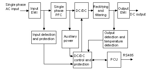
Operating principle diagram of rectifier
Major Functions of ER22005/S(ER11010/S)
1. Input over/under-voltage protection
The rectifier is capable of over/under-voltage protection. When the input voltage is higher than the input overvoltage set point, the rectifier will be shut down for protection. There will be no DC output and the protection indicator (yellow) will turn on. When the input voltage is lower than the input undervoltage set point, the rectifier will be shut down for protection. There will be no DC output, and the protection indicator (yellow) will blink. The rectifier will return to normal operating and the operating indicator (green) will turn on when the voltage returns to normal range.
2. Output over-voltage protection & under-voltage alarm
The rectifier is capable of output over-voltage protection and under-voltage alarm. When the output voltage is higher than the output overvoltage set point, the rectifier will shut down, with no output, and the alarm indicator (red) will turn on. The rectifier cannot be auto-recovery. You need to power it off and on to restart it.
When the output voltage is lower than the output undervoltage set point, the alarm will be raised, but the rectifier will keep its output, and the operating indicator (green) will blink. This alarm will be cleared and the operating indicator (green) will turn on once the voltage restores to normal.
3. Short circuit foldback of output
The rectifier is capable of limiting output upon short circuit, during which the output current will be limited to 40% of rated output current. The output will restore to normal after the short is removed.
4. Over-temperature protection
The over-temperature protection will be triggered when the temperature is higher than the set point, either due to too high ambient temperature, or because rectifier air inlet is blocked. The alarm indicator (red) will turn on, and there will be no output. The rectifier will return to normal operating and the operating indicator (green) will turn on when the inner temperature of the rectifier returns to normal range.
5. Fan fault alarm
When the fan is blocked, the alarm indicator (red) will blink and the rectifier will shut down, with no output. The rectifier will return to normal operating and the operating indicator (green) will turn on when the fault is cleared.
6. Fan speed control
The rectifier is capable of stepless fan speed control, determined by taking both temperature and output current into consideration.
7. Communication function
The rectifier can communicate with the host through RS485 port. It can report to the host its output voltage, current, protection and alarm information, as well as receive and execute control commands from the host. See the following table for details.
Rectifier communication function
|
No.
|
Item
|
Specification
|
|
1
|
Remotely acquiring alarm/digital signal
|
Report to the PCU the fault and protection signals (such as AC over/under-voltage, output over/under-voltage, and over-temperature)
|
|
2
|
Remotely acquiring analog signal
|
Measure the output voltage and current of the rectifier and report them to the PCU
|
|
3
|
Remotely controling system state
|
Control the rectifier power on/off and float charging / boost charging switchover according to the PCU
|
|
4
|
Remotely adjusting voltage analog signal
|
Adjust the output voltage of rectifier according to the PCU
|
|
Adjust the output current limit of rectifier within the range of 10% ~ 100% according to the PCU
|