DC Power
DC Power System
index > DC Power > DC Power System
Intelligent High-frequency Switch Mode Electric Power System with Integrated Cabinet system Structure
editor:admin date:2014-07-22
PowerMaster series intelligent high-frequency switch mode electric power system (for short, power system) is a highly reliable product developed by Emerson Network power Co. Ltd. based on its years of development experience. The system components include the input power distribution, rectification, DC output, monitoring system, insulation status detection and battery detection. It is applicable to power plants, hydropower stations, substations, and switching stations, providing DC power for circuit breaker switching, and for other equipment, meters, protection relays and illumination.
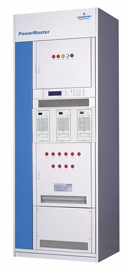
The structure of the integrated cabinet with 3 HD22010-3 rectifiers is shown in Figure Integrated cabinet system structure. The system structure slightly varies with different rectifier models and numbers, but the overall layouts are the same.
The integrated cabinet system is applicable to the single bus system with single battery string, single charger, 24 or less output branches (each branch capacity being less than 63A), and battery capacity of less than 150Ah. In the actual application, the small substation users can install the DC/DC, AC/DC or DC/AC inverter of the small capacity –48V communication power system into the cabinet, right at the spare rectifier’s slot.
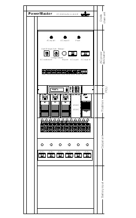
Integrated cabinet system structure
System Operation Principle
The power system comprises the AC input distribution, rectification, DC output distribution, and monitoring system. The four parts are in turn made up of different components as shown below:
1) AC input distribution: AC distribution cabinets.
2) Rectification: rectifiers and insulation diodes.
3) DC output distribution: diode chain, IMS, switching branches (connected to the switching bus), and control branches (connected to the control bus).
4) Monitoring system: power control unit (PCU) and distribution monitoring box.
The operation theory is shown in the following figure.
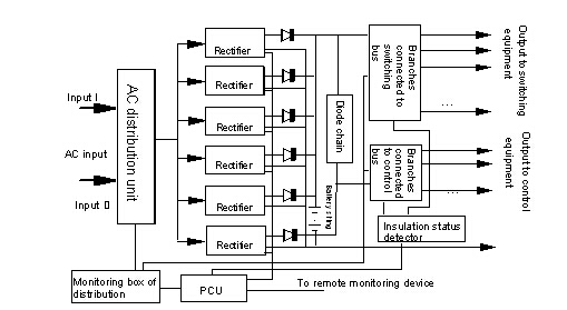
Electric power system operation theory
Upon normal AC input, one of the two AC inputs is selected by the AC switchover control circuit and powers the rectifiers through the AC distribution unit. The rectifiers convert the 3-phase AC into 220V or 110V DC and parallel output it through the isolation diodes. The DC output then charges the batteries and powers the load through the switching branches and control branches.
Upon AC input interruption or abnormality, the rectifiers will stop working, and the battery will power the load through the switching branches and control branches. The rectifiers will restore to normal operation and charge the batteries after the AC input restores.